What Is PWHT? Post Weld Heat Treatment — Definition, ASME Requirements, and the Role of Tempilstik®
Post Weld Heat Treatment (PWHT) is a controlled thermal cycle applied to welded structures after the weld has cooled to ambient temperature. It is mandatory under ASME and EN codes for many alloy steels and thick-section components. Unlike preheat or interpass temperature control, PWHT is not performed during welding — it is an independent heat treatment cycle: heat to a specified temperature, hold for a defined soaking time, then cool in a controlled manner.
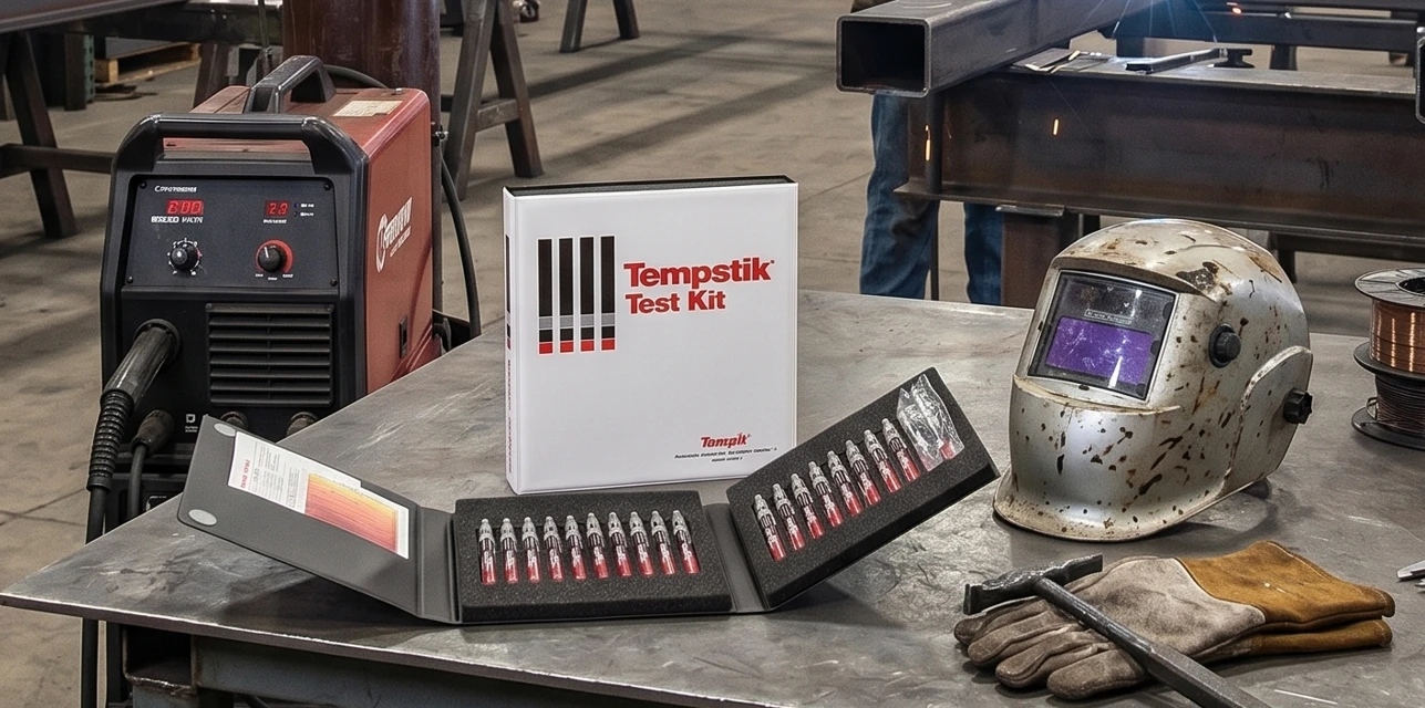
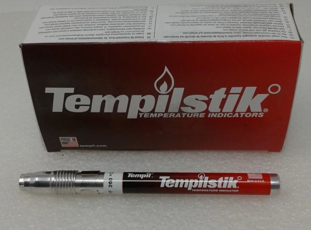
Thermocouples and data loggers are the primary instruments for recording PWHT. However, Tempilstik® temperature indicating crayons play a defined role as a spot-check tool — confirming that the actual surface of the component has reached the required temperature at locations where thermocouple coverage does not extend.
What Is PWHT — Metallurgical Definition and Purpose
PWHT is a controlled heating cycle applied to a welded assembly after the weld joint has fully cooled to ambient temperature (or to a specific temperature dictated by the applicable code). The technical purpose of PWHT is not a single objective — it simultaneously addresses three metallurgical problems created by the welding thermal cycle:
- Stress relief: Welding creates extreme temperature gradients over very short time intervals. The base metal expands and contracts non-uniformly, generating internal residual stresses — sometimes approaching the yield strength of the material. PWHT at sufficient temperature softens the crystal lattice, permitting limited plastic deformation that releases these stresses.
- HAZ property restoration for alloy steels: In Cr-Mo and Cr-Mo-V alloy steels, the welding thermal cycle creates hard, brittle martensite in the HAZ. PWHT tempering transforms martensite into bainite or sorbite — structures with substantially higher impact toughness, suited for high-temperature, high-pressure service conditions.
- Hydrogen diffusion: Although preheat supports hydrogen diffusion during welding, PWHT at elevated temperature drives this process more thoroughly, reducing the risk of delayed cold cracking after the joint has cooled.
Preheat vs. Interpass vs. PWHT — The Three-Stage Framework
While preheat and interpass temperature can be verified with Tempilstik® throughout welding, PWHT requires a more systematic data recording approach because temperatures are much higher and soaking time must be documented fully to satisfy third-party inspection requirements.
PWHT Temperature Requirements — ASME P-Number Classification
ASME classifies materials by P-Number to prescribe PWHT requirements. The table below covers the most commonly encountered steel grades in Vietnamese refining, petrochemical, and power generation applications:
ASME PWHT (Stress Relief) — Minimum Soaking Temperature and Hold Time by P-Number
| P-Number (ASME) | Typical Material | Common Spec | PWHT Temperature Range | Minimum Soaking Time | Tempilstik® Spot-Check |
|---|---|---|---|---|---|
| P1 | Carbon steel | A106 Gr.B, A53, A516 | 580–620°C (1076–1148°F) | 1 hr per 25 mm thickness | #28047 (600°F / 316°C) — verify temperature reached |
| P4 | 1¼Cr–½Mo steel | A335 P11 | 600–650°C (1112–1202°F) | 1 hr per 25 mm | #28047 + #28057 (1022°F / 550°C) |
| P5A | 2¼Cr–1Mo steel | A335 P22 | 700–760°C (1292–1400°F) | 2 hr minimum per 25 mm | #28057 + #28065 (1450°F / 788°C) |
| P5B (P91) | 9Cr–1Mo-V steel | A335 P91 | 730–760°C (1350–1400°F) | 1 hr minimum per 25 mm | #28065 (1450°F / 788°C) — mandatory |
| P8 | Austenitic stainless | A312 TP304, TP316 | Solution anneal 1040–1120°C | Standard stress relief not applicable | Outside standard Tempilstik® range |
The Role of Tempilstik® in PWHT Operations
A frequently asked question from QA/QC engineers: "We already have thermocouples and a data logger — what does Tempilstik® add to PWHT?" The answer lies in the fundamental difference between the two measurement methods.
Thermocouples measure temperature at a fixed contact point — typically at or near the weld surface as specified in the PWHT WPS. The data logger creates a continuous time-at-temperature record, which is the primary evidence for the QA file.
However, thermocouples cannot cover every surface area of a complex component — particularly in fittings, thick flanges, nozzle reinforcement pads, and recessed geometries. Tempilstik® fills these gaps:
- Spot-check at thermocouple-free locations: Mark the flange face, nozzle base, or fitting corner — if the crayon melts, that location has reached the required temperature.
- Rapid confirmation before starting the soaking time clock: Before the inspector begins the soaking time count, a quick Tempilstik® sweep of the points furthest from the heat source confirms that the entire component is uniformly at temperature.
- Supplementary evidence when thermocouple data is in question: When the data logger shows anomalous readings or a thermocouple has become detached during heating, a melted Tempilstik® mark on the surface provides physical corroborative evidence for the QA record.
- Indirect heating rate monitoring: On large components, observing the sequence in which Tempilstik® marks at different temperature ratings melt reveals whether heat is distributing uniformly through the assembly.
In the QA file: a photograph of a melted Tempilstik® mark on the component surface, with notation of the part number, location, and time, is accepted by third-party inspectors (TPI) as supplementary evidence to the thermocouple record. Some owner specifications — including Shell DEP — explicitly require spot-check verification using a temperature indicating crayon.
Tempilstik® Part Numbers for PWHT Verification
The PWHT temperature range (580–760°C) falls within the Tempilstik® product range. The selection principle is: choose the part number whose rated temperature is at or below the minimum PWHT soaking temperature — when this crayon melts, you have confirmed the surface has reached the required level.
| Part Number | Temperature (°F / °C) | PWHT Application | Corresponding Steel Group |
|---|---|---|---|
| #28047 | 600°F / 316°C | Verify initial temperature rise — low checkpoint for P1 cycle | P1 (carbon steel) |
| #28057 | 1022°F / 550°C | Mid-cycle checkpoint for P4 and P5A heating | P4 (P11), P5A (P22) |
| #28061 | 1200°F / 649°C | Spot-check confirming surface above 649°C before P1 soaking begins | P1 (uniform heating verification) |
| #28065 | 1450°F / 788°C | Spot-check in P22 and P91 PWHT — confirm surface at ≥ 788°C before soaking | P5A (P22), P5B (P91) |
Combined usage strategy for P91 PWHT (target 730–760°C): Apply Tempilstik® #28065 (788°C) at the spot-check locations. When this crayon melts at all points, the entire component mass is confirmed above 788°C — sufficient indication for the thermocouple system to continue monitoring the soaking temperature. Note that no Tempilstik® is available in the 730°C range — this is why thermocouple data logging remains the primary instrument; Tempilstik® serves as the supplementary verification tool.
Frequently Asked Questions
Is PWHT mandatory for all welds, or only specific cases?
PWHT is not required for all welds. The requirement depends on three factors: material P-Number, base metal thickness, and the applicable code. P-No.1 carbon steel below certain thickness thresholds generally does not require PWHT under ASME B31.3. By contrast, P91 (P-No.15E) requires PWHT without any exception for thickness or joint size. Always verify against the applicable standard's PWHT table and the approved WPS.
How critical are heating rate and cooling rate in PWHT?
Both are critical — especially for alloy steels. Excessively rapid heating creates large thermal gradients that can crack thick sections. Excessively rapid cooling after PWHT can re-introduce residual stress or form undesirable microstructural phases. ASME B31.1 specifies a maximum heating rate of approximately 220°C/hour (400°F/hr) divided by the thickness in inches — thicker components must heat more slowly. Thermocouples and data loggers are mandatory to monitor and document both parameters.
Can PWHT be performed in the field rather than a furnace?
Yes — field PWHT is common practice in plant maintenance and pipeline installation. The most frequent methods are electric resistance heating (resistance heating elements wrapped around the weld zone) and induction heating. The requirements are identical: thermocouples, data logger, controlled heating and cooling rates, and documented soaking time. Tempilstik® is particularly practical for field PWHT because it requires no power supply and can be applied to any accessible surface area.
What documentation is required to close a PWHT QA record?
A complete PWHT record typically includes: (1) chart recorder or data logger output showing temperature versus time with inspector signature; (2) thermocouple count and positions per the WPS; (3) confirmation that soaking time met the minimum requirement; (4) heating and cooling rates within specified limits; (5) field photographs with weld identification numbers. Tempilstik® spot-check photographs provide useful supplementary documentation but do not replace the thermocouple time-at-temperature record.
Can Tempilstik® verify the actual soaking temperature at 600°C in PWHT?
Tempilstik® has product ratings extending to approximately 650°C (1200°F) in standard range. In practical PWHT operations at 580–760°C, Tempilstik® is used as a mid-cycle spot-check — confirming the component has passed through intermediate temperature thresholds during the heating phase. For precise confirmation that soaking temperature of 600–760°C is being maintained, thermocouples are the mandatory primary instrument and cannot be substituted.
Need Tempilstik® for a PWHT project or welding temperature control application? tempil.vn is the authorized Tempil® distributor in Vietnam — C/O, C/Q, and VAT invoice available. Sold by box of 10 or individually.
Request a Quote 0938 888 958