ASME B31.3 Preheat for Process Piping — P-Number Classification, Practical Guide & Tempilstik® Selection
ASME B31.3 Process Piping governs the majority of piping installation work in refineries, gas plants, chemical plants, and industrial processing facilities in Vietnam. Unlike AWS D1.1 — which classifies steel by Carbon Equivalent and wall thickness — ASME B31.3 classifies materials by P-Number, ASME's own grouping system based on chemical composition and mechanical properties. Understanding P-Number and its corresponding preheat requirements is a fundamental competency for welding engineers, welding inspectors, and QA/QC personnel in process piping work.
ASME B31.1 vs ASME B31.3 — Key Differences
These two codes are frequently confused, especially on projects that combine power generation with industrial processing systems:
| Criterion | ASME B31.1 — Power Piping | ASME B31.3 — Process Piping |
|---|---|---|
| Scope | Power plants: main steam lines, steam extraction, boiler feedwater | Refineries, chemical plants, gas processing, LNG, industrial process systems |
| Inspection authority | Authorized Inspector (AI) per B31.1 | Owner's Inspector per B31.3 |
| PWHT requirements | More stringent — mandatory PWHT at lower wall thicknesses | Higher thickness thresholds before PWHT is triggered |
| Typical applications in Vietnam | Steam turbine piping, power plant boiler systems | BSR (Dung Quat Refinery), PVFCCo, GPP gas processing plants |
| P-Number system | Identical — governed by ASME Section IX | |
P-Number System in ASME B31.3
The P-Number is ASME Section IX's material grouping number — the foundation for developing WPS documents and determining preheat and PWHT requirements. The following table covers the P-Numbers most commonly encountered in process piping in Vietnam:
| P-Number | Material Group | Typical Grade | Min Preheat (B31.3) | Tempilstik® Part No. |
|---|---|---|---|---|
| P-No.1 | Carbon steel | A106 Gr.B, A53 Gr.B, API 5L Gr.B | 10°C (t < 25 mm) / 79°C (t ≥ 25 mm) | #28009 (175°F / 79°C) |
| P-No.1 (heavier section) | Higher-carbon grade | A106 Gr.C, heavy wall | 79°C / 121°C | #28009 / #28019 |
| P-No.3 | Low-alloy (0.5Mo) | A335 P1, A161 T1 | 79°C (175°F) | #28009 |
| P-No.4 | Low Cr-Mo (1.25Cr-0.5Mo) | A335 P11, A213 T11 | 150°C (302°F) | #28318 |
| P-No.5A | Medium Cr-Mo (2.25–3Cr) | A335 P22, A335 P21 | 200°C (392°F) | #28327 |
| P-No.5B | High Cr-Mo incl. P91 (5–9Cr) | A335 P91, A335 P9 | 200°C (392°F) | #28327 |
| P-No.8 | Austenitic stainless steel | A312 TP304, TP316, TP321 | No preheat required | — |
Case Study: Welding A106 Gr.B 6-inch Schedule 80 Pipe to a Class 600 Flange
This is one of the most common field situations in process piping — welding a pipe to a flange that is substantially thicker than the pipe wall. Preheat determination is more complex because the two components have significantly different wall thicknesses.
Component specifications
| Component | Material | Standard | Thickness at weld |
|---|---|---|---|
| Pipe | ASTM A106 Gr.B — DN 6" (168.3 mm OD) Sch.80 | P-No.1 | 10.97 mm |
| Flange | ASTM A105 — Class 600 — DN 6" (hub at weld bevel) | P-No.1 | ~38 mm |
Step-by-step preheat determination
- Confirm P-Number: Both A106 Gr.B (pipe) and A105 (flange) are P-No.1 (carbon steel). WPS: P-No.1 to P-No.1.
- Determine governing thickness: Per ASME B31.3, when the two components have different thicknesses, preheat is determined by the greater thickness at the weld joint. The Class 600 DN 6" flange hub at the bevel is approximately 38 mm.
- Apply Table 330.1.1: P-No.1 with t ≥ 25 mm → minimum preheat 79°C (175°F).
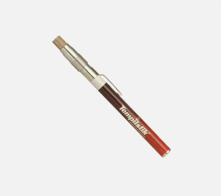
- Select Tempilstik®: Part #28009 (175°F / 79°C).
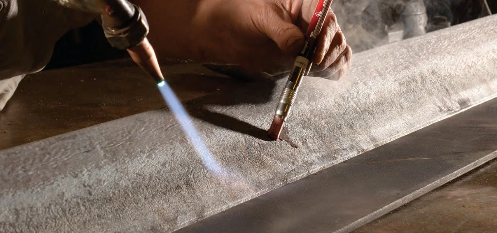
Field measurement sequence
- Heat the full pipe circumference and flange hub using resistance heating wire or propane torch.
- Mark Tempilstik® #28009 at positions at least 75 mm from the weld bevel on the pipe side — at 4 evenly distributed points (0°, 90°, 180°, 270°).
- Also mark the flange hub face — the thickest point, farthest from the heat source, slowest to reach temperature.
- Begin welding only when all measurement points show the crayon has melted — confirming uniform preheat across the full joint.
- Document in the Preheat Record (ITR): time, temperature, measurement method (Tempilstik® #28009), measurement locations, inspector name.
PWHT Requirements per ASME B31.3
ASME B31.3 defines wall thickness thresholds above which PWHT becomes mandatory for each P-Number. This is the second most important parameter after preheat:
| P-Number | Wall Thickness Requiring PWHT (B31.3) | PWHT Temperature | Tempilstik® Spot-Check |
|---|---|---|---|
| P-No.1 | t > 19 mm (¾") | 595–650°C (1103–1202°F) | #28047 (316°C) — heating phase checkpoint |
| P-No.4 | All thicknesses | 675–760°C (1247–1400°F) | #28057 (550°C) |
| P-No.5A | All thicknesses | 675–760°C (1247–1400°F) | #28057 (550°C) |
| P-No.5B (P91) | All thicknesses — no exceptions | 730–760°C (1346–1400°F) | #28065 (788°C) |
| P-No.8 | Not applicable | — | — |
For full PWHT procedure details, soaking time requirements, and the role of Tempilstik® in heat treatment verification, see PWHT — Post Weld Heat Treatment.
Frequently Asked Questions
Need Tempilstik® for ASME B31.3 process piping projects?
Fast Group Engineering — authorized Tempil® distributor in Vietnam. Free P-Number to part number consultation. C/O + C/Q + VAT invoice. Stock in HCMC and Vung Tau.
📞 +84 938 888 958 | ✉ sales@tempil.vn